Highlights from my professional and personal experience, organized from oldest to newest. Projects that I’m most proud of, or that I feel are most unique or important, are marked with a ⁕.
2026-2027 ACADEMIC YEAR
SENIOR DESIGN⁕ COMING SOON
SUMMER 2026
PROJECT
After having learned the basics of corridors, I assisted with early drafts for a series of roads in Glenview, IL that were scheduled for complete reconstruction in 2029.
MY TASK
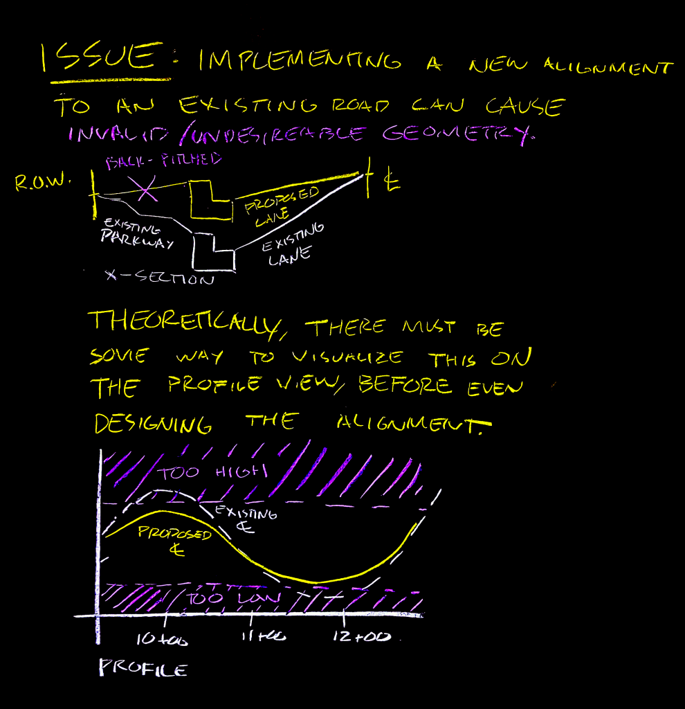
I was tasked with modeling corridors along several residential roads. The most challenging part of this was creating the vertical alignments. Among what I had to consider is the following:
Following maximum and minimum grade requirements and curve lengths along the corridor
Ensuring that driveways and parkways meet grade requirements
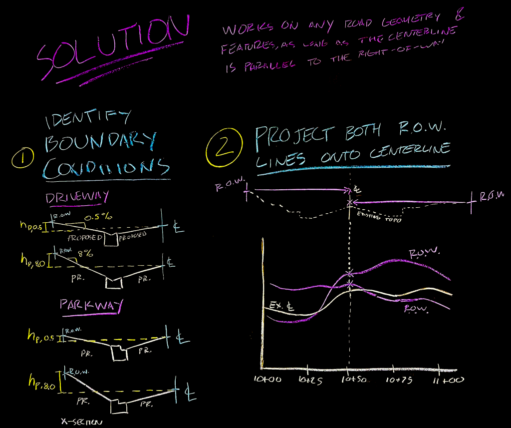
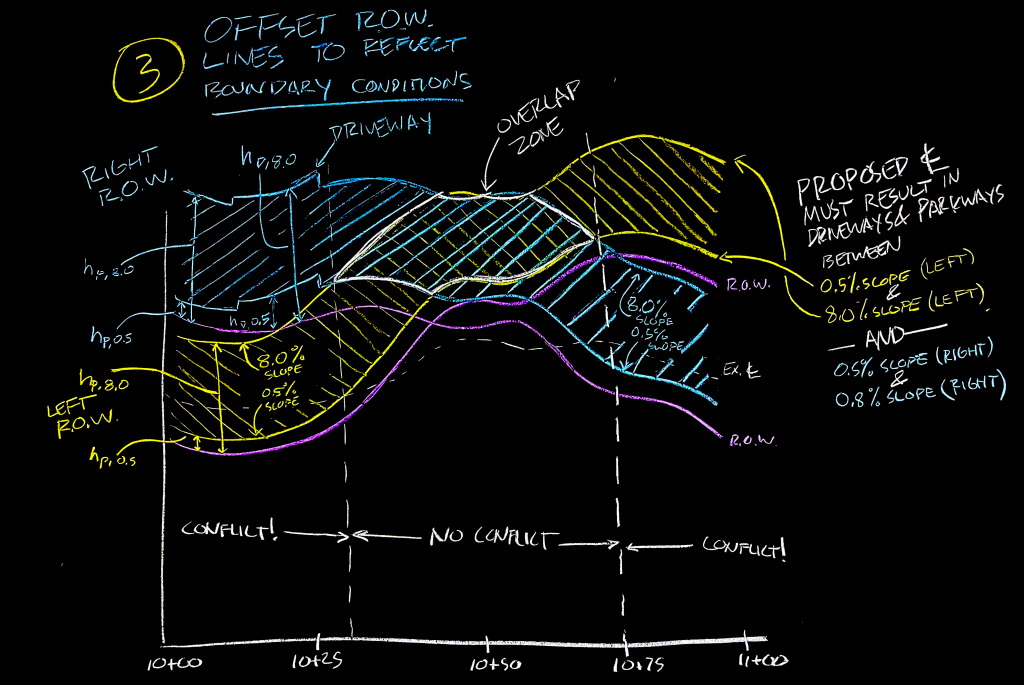
As far as I could tell, no method for meeting both of these criteria at once existed that didn’t involve drawing an initial ‘guess’ alignment and then adjusting from there. The issue with this approach is that, sometimes, these geometric constraints contradict each other, rendering it impossible to satisfy them all. When guessing and checking, it isn’t clear if/when this is the case. I theorized that there must be some way to visually prove when the criteria contradict each other. I was able to come up with the following workflow, which is hard to explain, so I illustrated it on a blackboard:
Glenview, IL
AUGUST 2026
MY TASK
Later in my internship at Baxter & Woodman, I was trusted with helping to develop a new spreadsheet system to process quantity data. The existing system was over-complicated and required extensive cross-checking between similar sheets, which wasted engineers’ time. Its formatting was inconsistent, and it wasn’t intuitive, either. My task was to simplify and streamline this experience for everyone involved.
MY SOLUTION
The system I came up with, and played a large part in the creation of, consists of input sheets and formatting sheets. Input sheets greatly reduce redundancy by providing a single source of values for a project. Formatting sheets, as the name suggests, serve to automatically reference input sheets and format them for clients or state departments while keeping the quantities in those sheets easily accessible and editable. After I made significant progress, I volunteered to present my work and my methodology to the transportation engineering department at Baxter & Woodman.
Glenview, IL
AUGUST 2026
MY TASK
A water main being replaced through several streets in Hanover Park, led to a large-scale resurfacing of several streets. Most of the curb ramps needed to be adjusted to fit with ADA standards.
WHAT I DID
drew in plans for curb ramps for several crosswalks, ensured that all crosswalks and curb ramps were ADA compliant
Shortened the length of crosswalks, reducing the amount of time needed to cross the street
SKILLS ACQUIRED
Familiarity with sidewalk designs and Bentley OpenRoads Designer
Hanover Park, IL
AUGUST 2026
MY TASK
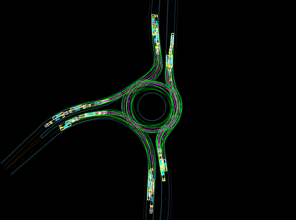
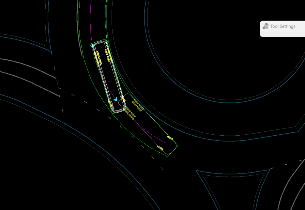
A roundabout in a late design stage needed to be checked for two design vehicles: a wide-body truck and a large bus.
WHAT I DID
I used AutoTURN to geometrically demonstrate each of the design vehicles moving through the roundabout in every configuration.
SKILLS ACQUIRED
Basic AutoTURN
JULY 2026
MY TASK
I assisted with a village-wide bicycle and pedestrian signage project. The contractor who put up signs charges by the square foot. I needed to efficiently total the square footage of signs in the plan sheet and update the associated quantities spreadsheet.
WHAT I DID
Marked up each sign with its MUTCD code on Bluebeam, then exported that into excel
Used colors to indicate what was being added and removed
Took advantage of advanced Excel functions to fetch data directly from the MUTCD
WHAT I LEARNED
Familiarized myself with the MUTCD
Learned to synergize Excel and Bluebeam
Glenview, IL
JUNE 2026
ISSUE
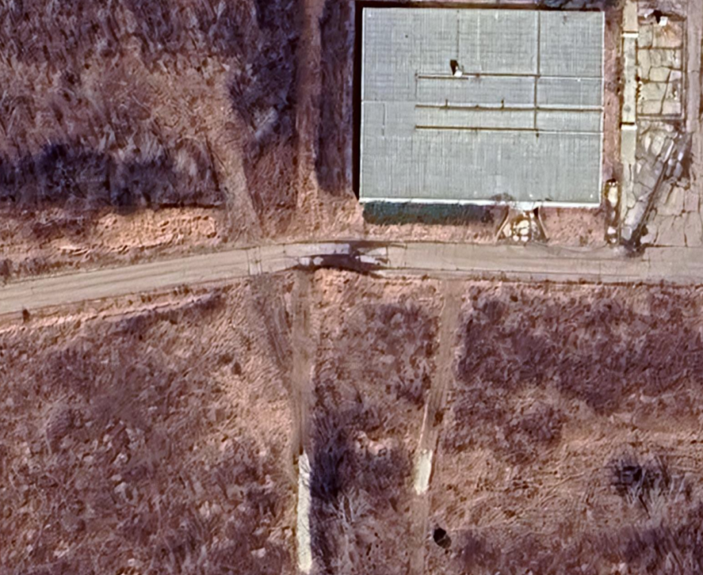
Improper grading at the bottom of a vertical curve caused drainage issues in this wastewater plant’s driveway. A complete reconstruction was deemed necessary.
MY TASK
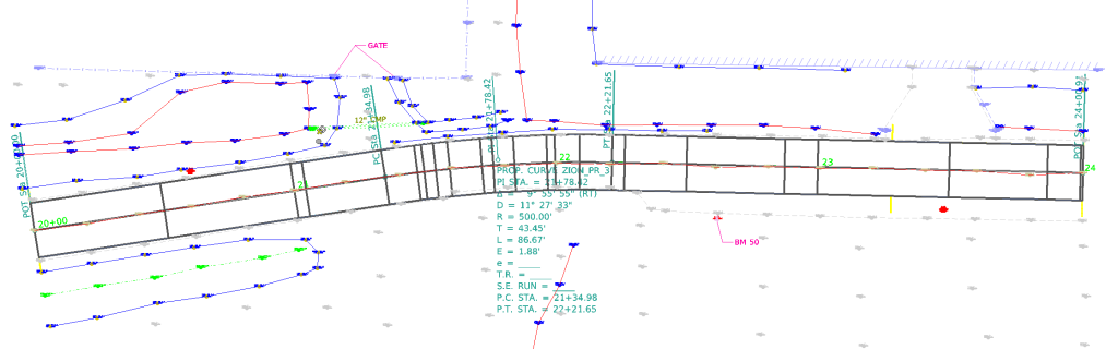
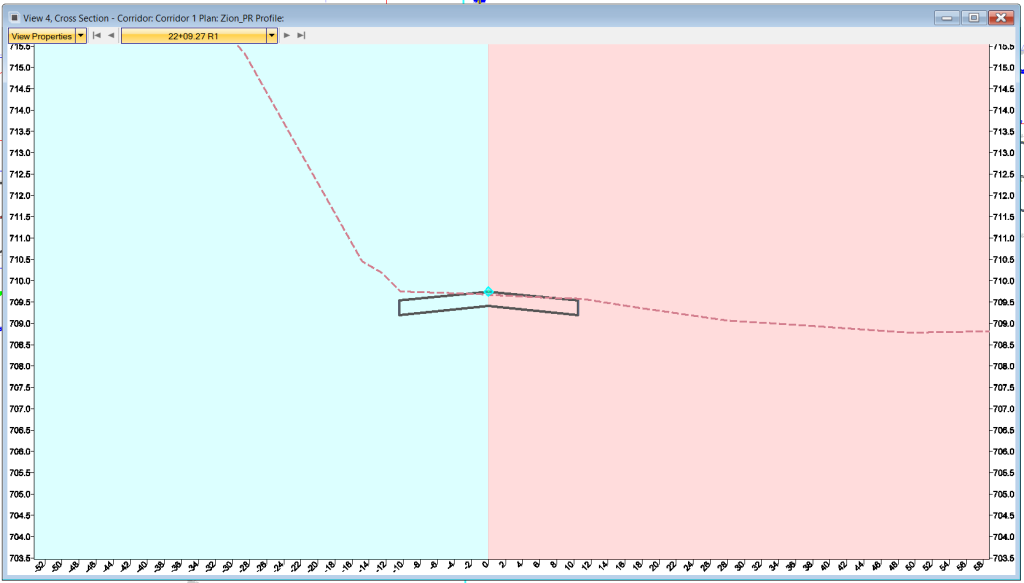
Create a basic corridor model, in Microstation V8i, containing the proposed horizontal and vertical alignments as well as a cross-section
Design the corridor to drain properly while minimizing earthwork and ensuring that both ends of the proposed design meet up with existing topography
Familiarize myself with MicroStation’s layout and workflow
SKILLS ACQUIRED
Basic MicroStation corridor modeling
Improved my vocabulary around concepts I already knew
42.482819, -87.890589
JUNE 2026
2025
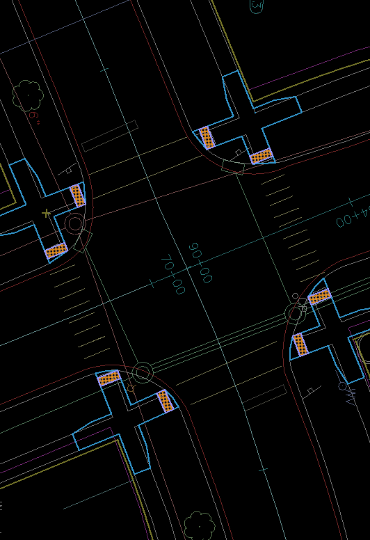
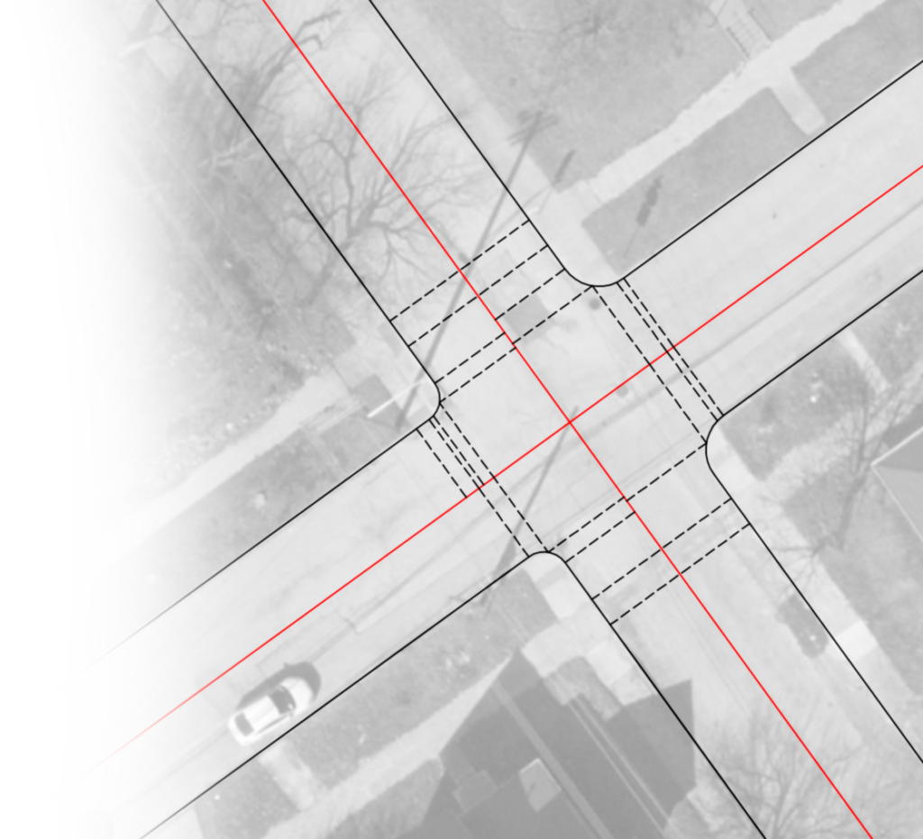
As a roadway design intern at Lochmueller Group, I created construction drawings of many intersections along Tipton Street in Huntington, Indiana. These drawings were a part of the greater Huntington LTCP, which included plans for the street to be repaved and redesigned. One of the tasks I was given was turning the roadway CAD files into drawings of each intersection usable for construction.
I noticed that the intersections were all qualitatively similar, only consisting of straight lines and simple arcs, so I made a single parametric AutoCAD smart block that could be dragged and snapped to the size and orientation of each intersection.
Improving this workflow saved me, and others working on the same task, hours of time and effort.
Huntington, IN
JUNE 2025
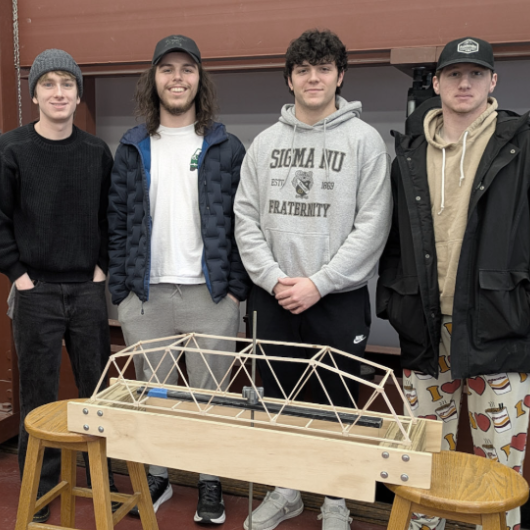
For the final project of Mechanics of Materials, me and three of my classmates were tasked with designing and constructing a bridge out of balsa wood. It would be evaluated based on strength to weight ratio.
Thanks to our unique design approach, our bridge was able to support three hundred times its weight.
analysis & design
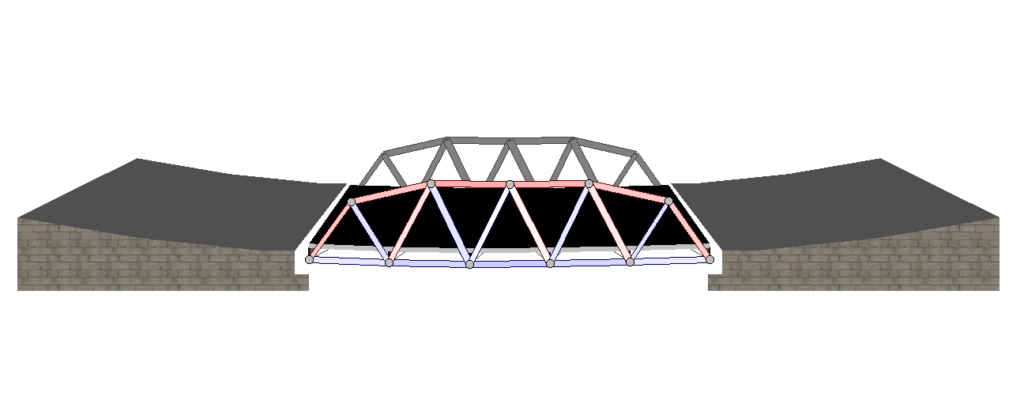
This project is meant to be an introduction to tension & compression member design. As such, the structural analysis software we were given was West Point Bridge Designer, a program that can calculate axial force in each member of a simple steel bridge truss.
Because our main design criteria was strength to weight ratio, we made the decision to consider the members’ axial stresses only in relation to each other. We theorized that, by choosing our cross-sectional areas correctly, we could normalize the stress in each member, such that every member would fail at once. This approach helped us greatly minimize excess material.
construction
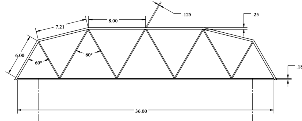
After we’d settled on the shape of our truss and the cross-sectional area of each member, I accepted the task of creating a precise CAD drawing of our truss.
The details of our connections were laid out such that almost every member was an integer length. The tools that we had could only cut angles at 30°, 45°, 60°, and 90°, so joints were all planned with that in mind. In addition, I printed scale diagrams of each member on paper for ease of fabrication and auditing.
My efforts made our construction process fast and precise, saving my team significant time and effort over the duration of the project.